 |
Clear Springs Press |
|
|
Clear Springs Press |
We would all like a transmission line that has no loss, matches the antenna and transmitter perfectly, weighs nothing, and takes up no space. Let's start with low loss.
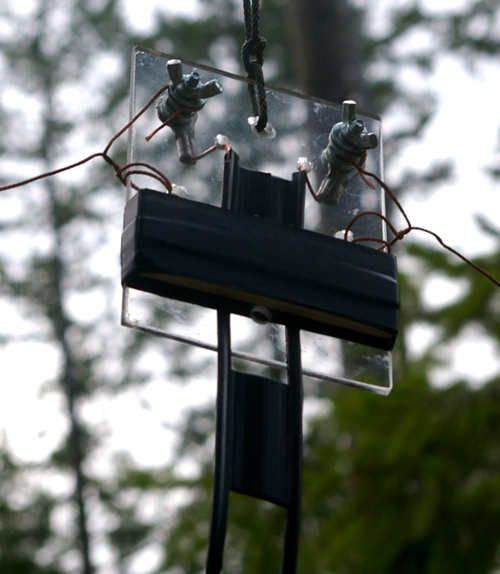
The transmission line shown in the photo is 450 ohm window line. 450 ohm window line has very low loss, even in the presence of very high SWR.
The center insulator, in this example, is made from a small piece of plexiglas or similar material. The wingnuts make it easy to attach and detach the wire from the reels. Strain relief for the feedline is provided by sandwiching it with a thin strip of plastic or wood and binding it with stretchy electrical tape.
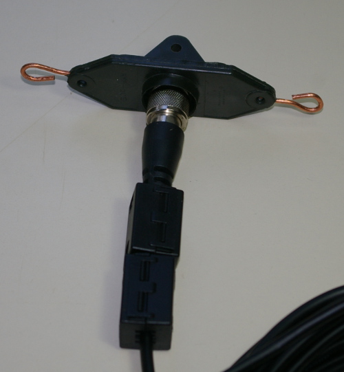
The transmission line in this photo is RG-58 coax attached to a center insulator. There are two ferrite cores clamped around the cable to restrict unbalanced current in the coax shield and inhibit feedline radiation (a choke balun). The attachment of two wires of resonant length to the center insulator forms a resonant dipole antenna when suspended at an appropriate height.
The three primary types of feedline applicable to portable operation are coaxial, twinlead and ladder line. Open wire transmission line provides the lowest losses, but is more difficult to manage if you have to constantly roll and unroll it. The objective is to choose the line that:
Transmission line loss calculations are complex and are affected by the environment and operating parameters. The formulas for doing the calculations can be found in the books in the reference section.
To get a perspective on what the transmission line losses are likely to be under portable operating conditions consider the following examples. Transmission line lengths chosen are 22 ft. for low height and NVIS deployments and 42 ft. for higher deployments.
For Feedline length of 42 ft. and an SWR of 10:1, the loss in RG-174U is 4.69 dB on 10 meters, while it is only 1.83 dB when the SWR is 1:1.
For Feedline length of 42 ft. and an SWR of 10:1, the loss in RG-8X is 2.48 dB on 10 meters, while it is only 0.67 dB when the SWR is 1:1.
For Feedline length of 42 ft. and an SWR of 10:1, the loss in 300 ohm twinlead is 1.06 dB on 10 meters, while it is only 0.24 dB when the SWR is 1:1.
For Feedline length of 42 ft. and an SWR of 10:1, the loss in 450 ohm ladder line is 0.31 dB on 10 meters, while it is only 0.06 dB when the SWR is 1:1.
For Feedline length of 42 ft. and an SWR of 10:1, the loss in RG-174U is 2.42 dB on 80 meters, while it is only 0.65 dB when the SWR is 1:1.
For Feedline length of 42 ft. and an SWR of 10:1, the loss in RG-8X is 0.79 dB on 80 meters, while it is only 0.24 dB when the SWR is 1:1.
For Feedline length of 42 ft. and an SWR of 10:1, the loss in 300 ohm twinlead is 0.42 dB on 80 meters, while it is only 0.09 dB when the SWR is 1:1.
For Feedline length of 42 ft. and an SWR of 10:1, the loss in 450 ohm ladder line is 0.12 dB on 80 meters, while it is only 0.02 dB when the SWR is 1:1.
When the feedline length is reduced to one half, the losses in dB are also reduced by one half.
To get a feel for what this means in practical terms, note that 1 dB difference in signal strength will probably not be noticed by an operator while 3 dB represents half of the transmitter power or received signal strength.
What one can conclude from this is:
In terms of lowest losses, the 450 ohm window line is the clear winner, especially where the SWR may be large as with random length dipoles, long wire antennas, and some highly directional high gain antennas like rhombics that may have high impedance and high SWR. When using ladder line, you will also have to use a matching balun and/or tuner, usually both, in order to match the impedance to the 50 ohm output of a transmitter. For the total loss, one must add the dB losses of the tuner, balun and transmission line. While the transmission line losses are predictable and the losses in a well designed balun are generally modest, estimating the losses in an antenna tuner is more difficult. In general, the tuner losses are lower if it uses high Q air core coils rather than ferrite core coils which are more compact. In general, tuner losses are lower when the impedance mismatch is smaller. In practice, antenna tuner manufacturers do not specify the loss characteristics of their products. This is because there are a lot of variables and no one has written any standards against which comparisons can be made.
In situations where large SWR differences between the antenna and feedline exist, the feedline length can become critical. Certain lengths of feedline can result in very high impedance on some bands. To avoid problems, the following recommendations have been made by a number of authors and sources: (See the Reference section.)
To avoid problems matching or feeding any dipole antenna with a high impedance feedline, keep the lines around these lengths.
Back to the
Table of Contents
Purchase this book or read it FREE on Amazon Prime